
Blog
What Is the Fire Temperature Range of Lithium-Ion Batteries
2026-05-31 | Calvin
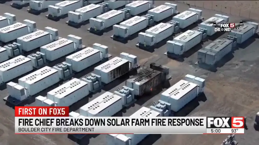
In June 2024, a lithium battery energy storage system in Moss Landing, California burned for days. In 2023, a single electric bus in Seoul ignited in an underground garage and destroyed 140 vehicles. In 2021, a residential solar installation fire in Chandler, Arizona required 14,000 gallons of water and took hours to extinguish.
These are not freak accidents. They are the predictable result of thermal runaway — the chain reaction failure mode that is intrinsic to lithium-ion battery chemistry when it encounters the wrong conditions at the wrong time. Understanding it is not optional for anyone who owns, installs, designs, or manages lithium battery systems.
This guide covers everything: the precise temperature stages of thermal runaway, the chemistry that drives each stage, how onset temperatures differ by battery chemistry (with peer-reviewed data), every trigger category, how fires from lithium batteries differ fundamentally from conventional fires, what firefighting approaches actually work, and a complete multi-layer prevention framework.
Part 1: What Is Thermal Runaway?
Thermal runaway is a self-accelerating failure condition in which a battery cell generates heat faster than it can dissipate it. The excess heat accelerates the exothermic chemical reactions inside the cell, which generates more heat, which accelerates the reactions further — a positive feedback loop that, once initiated beyond a critical threshold, cannot be stopped by simply removing the trigger.
The core physics: lithium-ion batteries store electrochemical energy in a chemically reactive system. Under normal operation, that energy is released in a controlled, useful way. Under thermal runaway, it is released uncontrollably as heat — and at extreme temperatures, as fire.
The cascade has two important properties that make it uniquely dangerous:
Self-sustaining: Unlike a conventional fire that requires an external fuel source and can be extinguished by removing oxygen or fuel, a battery in thermal runaway is simultaneously its own fuel and its own ignition source. The internal chemical reactions continue generating oxygen and heat even after external flames are suppressed. This is why lithium battery fires reignite hours — and in documented cases, days — after appearing to be extinguished.
Propagating: In a multi-cell battery pack, the intense heat from one failing cell transfers to adjacent cells, driving them into thermal runaway in turn. This cell-to-cell propagation is the mechanism behind the catastrophic fires seen in EV packs and large battery energy storage systems (BESS).
Part 2: The Five Stages of Thermal Runaway — Temperature by Temperature
Thermal runaway is not a single event. It is a sequential failure cascade with distinct stages, each triggered by the temperature reached in the previous stage. Understanding the stages allows system designers and operators to identify intervention points — the earlier in the cascade an intervention occurs, the more likely it is to succeed.
Stage 1: Normal Operation → Heat Accumulation (20°C–80°C)
In this stage, the battery is operating but heat generation is exceeding heat dissipation — either because the environment is too hot, the discharge rate too high, the cooling system inadequate, or some combination. The battery temperature rises steadily but no irreversible damage has yet occurred.
Key threshold: 45–60°C — Above this range, calendar aging accelerates significantly and the risk of entering Stage 2 begins increasing. Most BMS high-temperature alarms trigger in this range (typically at 50–60°C).
Intervention here is straightforward: reduce load, improve cooling, move the battery to a cooler environment. No chemistry has been damaged yet.
Stage 2: SEI Decomposition (80°C–130°C)
The Solid Electrolyte Interphase (SEI) is a thin passivation layer that forms on the anode surface during the first charge cycle. It is essential — it stabilizes the interface between the lithium-intercalated graphite anode and the organic electrolyte, preventing direct chemical reaction.
At approximately 80–120°C, the SEI layer begins to decompose. This is the first point of no-return: as SEI breaks down, the reactive anode material is progressively exposed to the electrolyte, triggering exothermic reactions that generate additional heat and flammable gases. The battery's self-heating rate increases — slowly at first, then accelerating.
Key chemical output: Flammable hydrocarbon gases (ethane, methane, CO). These accumulate inside the sealed cell, building internal pressure. In well-designed cells, a pressure relief vent activates to release this gas before pressure causes case rupture.
External warning signs at this stage: The battery case may begin to swell as internal pressure builds. A faint smell, unusual warmth to the touch, or voltage instability may be detectable. BMS temperature alarms at the cell level may trigger.
Intervention: At this stage, aggressive cooling and immediate load disconnection can still potentially halt progression. A well-designed BMS should have already disconnected the battery before this point.
Stage 3: Separator Failure and Internal Short Circuit (~130°C)
The polymer separator — the thin membrane between the anode and cathode that prevents direct contact while allowing ion transport — begins to soften and melt at approximately 120–140°C for standard polyethylene separators (some advanced ceramic-coated separators survive to higher temperatures).
When the separator fails, the anode and cathode make direct contact, creating an internal short circuit. This dumps the remaining stored energy across an essentially zero-resistance path, generating an enormous heat pulse almost instantaneously. The temperature spike from separator failure can jump 50–100°C in seconds.
This is the critical transition point — once the separator has failed and an internal short circuit is established, thermal runaway progression becomes extremely rapid and very difficult to arrest.
Stage 4: Electrolyte Decomposition and Cathode Oxygen Release (150°C–300°C)
With internal temperature now rising rapidly, two parallel destructive processes accelerate:
Electrolyte decomposition: The organic solvents in the electrolyte (typically ethylene carbonate, dimethyl carbonate, and similar compounds) decompose at high temperatures, releasing additional flammable gases — primarily hydrogen (H₂), carbon monoxide (CO), and methane (CH₄) — along with toxic byproducts including hydrogen fluoride (HF) from decomposition of the lithium hexafluorophosphate (LiPF₆) salt.
Cathode oxygen release: The oxygen release temperature and quantity depend critically on battery chemistry:
- NMC cathodes (layered oxide structure) begin releasing oxygen at approximately 150–250°C. This oxygen mixes with the flammable gases already present, providing the oxidant for combustion.
- LFP cathodes (olivine crystal structure) are fundamentally more stable. Their phosphate-oxygen bonds are significantly stronger than the metal-oxygen bonds in NMC. LFP cathodes do not meaningfully release oxygen until temperatures exceed approximately 350°C — and even then, in smaller quantities.
This chemistry difference is the root cause of LFP's superior fire safety: without cathode oxygen release at moderate temperatures, the self-sustaining fire mechanism requires much higher temperatures to initiate.
Visible signs at this stage: Visible gas venting through pressure relief valves, white/grey smoke, audible hissing. The battery is now actively releasing flammable and toxic gases into the surrounding environment. Evacuation should have already occurred.
Stage 5: Thermal Runaway — Full Fire (300°C–1,100°C)
Once the flammable gas-oxygen mixture ignites, full thermal runaway is established. Peak temperatures during this stage range from approximately 500°C for LFP chemistry to over 1,000°C for high-energy NMC and NCA chemistries. In the most energetic events with high-Ni NMC cells, peak temperatures approaching 1,100°C have been documented.
At these temperatures:
- Aluminum battery components melt (melting point: 660°C)
- Structural components fail
- Cell-to-cell propagation occurs in battery packs, potentially engulfing hundreds of cells in sequence
- Jet venting events (burning gas ejected forcibly from cells) can project burning material meters from the battery
The fire rate of propagation matters enormously. Peer-reviewed research comparing NMC-811 and LFP in automotive battery packs found that thermal runaway propagation is nine times faster in NMC-811 cells and five times faster across the complete propagation interval compared to LFP cells. This difference in propagation speed is why LFP is the dominant chemistry in residential energy storage systems and electric buses where occupant safety time-to-evacuate matters.
Part 3: Chemistry-by-Chemistry Thermal Runaway Comparison
This is the data most guides obscure with vague language. Here are peer-reviewed onset temperatures and severity comparisons for the principal lithium chemistries:
| Chemistry | TR Onset Temperature (T1) | Separator Failure Temp. | Peak Fire Temperature | Oxygen Release | Propagation Speed |
|---|---|---|---|---|---|
| LFP (LiFePO4) | 250–350°C | ~130°C (separator) | 500–700°C | Minimal, >350°C | Slow |
| NMC (Nickel Manganese Cobalt) | 150–250°C | ~130°C (separator) | 700–1,000°C | Significant, 150–250°C | Fast |
| NCA (Nickel Cobalt Aluminum) | 150–200°C | ~130°C (separator) | 800–1,100°C | Significant, 150–200°C | Very fast |
| LCO (Lithium Cobalt Oxide) | 150–200°C | ~130°C (separator) | 700–1,000°C | Significant | Fast |
| LMO (Lithium Manganese Oxide) | 200–250°C | ~130°C (separator) | 600–900°C | Moderate | Moderate |
Sources: ScienceDirect comparative analysis (2025), ACS Chemical Health & Safety (2025), Journal of Power Sources (2025)
What the data means in practical terms
The separator (which fails at approximately the same temperature for all chemistries) does not determine chemistry-dependent safety differences — it creates the internal short circuit regardless.
The key difference is what happens after the separator fails. In NMC, the cathode immediately begins releasing oxygen at the cell's now-elevated temperature (150–250°C onset), providing the oxidant that sustains self-heating and combustion. The exothermic cathode decomposition reaction adds fuel to the fire at the precise moment the internal short circuit is generating maximum heat. The two events compound catastrophically.
In LFP, after separator failure and internal short circuit, the cell heats further — but the olivine cathode structure does not release meaningful oxygen until temperatures approaching and exceeding 350°C. This means the LFP cell must reach a significantly higher temperature before the self-sustaining fire mechanism engages, giving the system more time for intervention and making thermal runaway inherently less likely to escalate to full fire.
This is not a theoretical difference. The onset temperature for thermal runaway in LFP batteries typically ranges from 250 to 350°C. In contrast, NCM cathodes generally initiate intense exothermic reactions between 150 and 250°C.
Part 4: Thermal Runaway Triggers — Complete Classification
Category 1: Electrical Abuse
Overcharging is the single most common electrical trigger. When a cell is charged beyond its rated maximum voltage (4.2V for NMC, 3.65V for LFP), lithium metal begins depositing on the anode surface (lithium plating) rather than intercalating properly. Metallic lithium is significantly more reactive than intercalated lithium. Simultaneously, the cathode is driven to high delithiation states where oxygen release begins at lower temperatures. Overcharging also accelerates electrolyte oxidation at the cathode.
Over-discharging drives the anode to excessively low states of charge where copper current collector dissolution can occur. Dissolved copper then re-deposits as metallic dendrites that can pierce the separator on the next charge cycle.
External short circuit (direct terminal-to-terminal short) forces extremely high discharge currents — potentially hundreds to thousands of amps — through the cell, generating massive I²R heat almost instantaneously. Cell temperature can reach SEI decomposition temperatures within seconds.
Lithium dendrite formation from repeated charge cycles, especially at high rates or low temperatures, produces needle-like metallic lithium growths on the anode that can penetrate the separator, causing internal short circuits. This is the aging-related failure mechanism most commonly responsible for spontaneous thermal runaway events in batteries with no apparent external trigger.
Category 2: Mechanical Abuse
Penetration/puncture forces a direct internal short circuit at the puncture site, creating an immediate, intense localized heat source. The severity depends on state of charge at the time of penetration — a fully charged cell penetrated by a nail or metallic debris releases far more energy than a depleted cell.
Crush/deformation from collision, compression, or impact forces the anode and cathode into direct contact across the deformed area. Even without complete penetration, significant deformation can fracture the separator and create contact patches.
Vibration fatigue is a long-term mechanical abuse mode relevant for automotive and marine applications. Repeated mechanical stress can eventually cause electrode delamination, separator damage, or tab connection failures that create intermittent internal short circuits.
Category 3: Thermal Abuse
External heat exposure from fire, proximity to heat sources (engine bay heat in poorly installed vehicle batteries), direct sun in enclosed spaces, or industrial heat environments can drive battery temperature into Stage 2 without any internal electrical fault.
Inadequate thermal management in battery packs — insufficient cooling capacity for the operating load and environment, cooling system failures, or blocked airflow — allows heat to accumulate during normal operation until temperatures reach dangerous levels.
Thermal propagation from adjacent cells — in battery packs, a single cell entering thermal runaway heats neighboring cells through direct conduction, radiation, and hot gas venting. Without adequate thermal barriers between cells, this creates the cell-to-cell propagation cascade.
Category 4: Manufacturing Defects
Metallic particle contamination — microscopic metallic particles introduced during electrode coating or assembly can cause immediate internal short circuits at initial charge. This is a known root cause of certain spontaneous failures in new batteries and why established manufacturers with rigorous quality control command premium prices.
Separator defects — pinholes or thin spots in the separator create weak points that can fail under normal operating conditions.
Electrolyte contamination — moisture or other contaminants in the electrolyte react with LiPF₆ to form corrosive HF, attacking electrode structures and accelerating degradation.
Part 5: The Toxic Gas Hazard — What Thermal Runaway Produces
Thermal runaway is not just a fire hazard. The gases produced during venting and combustion are a serious independent threat — to occupants, first responders, and the environment.
Gas species released during thermal runaway:
| Gas | Source | Hazard |
|---|---|---|
| Hydrogen fluoride (HF) | LiPF₆ electrolyte salt decomposition | Extremely toxic; IDLH (Immediately Dangerous to Life and Health): 30 ppm; causes severe burns to airways |
| Carbon monoxide (CO) | Incomplete combustion of electrolyte | Toxic asphyxiant; IDLH: 1,200 ppm |
| Hydrogen (H₂) | Anode reaction with electrolyte | Highly flammable; creates explosive atmosphere |
| Methane (CH₄) | Electrolyte decomposition | Flammable; asphyxiant at high concentrations |
| Ethylene (C₂H₄) | Electrolyte solvent decomposition | Flammable |
| Carbon dioxide (CO₂) | Combustion product | Asphyxiant at high concentrations |
| Phosphoryl fluoride (POF₃) | LiPF₆ decomposition | Highly toxic |
The HF hazard is frequently underappreciated. A single automotive EV battery pack can release hundreds of grams of hydrogen fluoride during a full thermal runaway event. HF is one of the most hazardous industrial chemicals — it penetrates skin without immediate pain, causing deep tissue destruction and systemic fluoride toxicity that can be fatal. First responders approaching EV fires and battery storage incidents require full SCBA (self-contained breathing apparatus) regardless of whether visible flames are present.
Gas production begins before visible fire. Battery venting during Stages 2–3 releases combustible and toxic gases before ignition. The gas cloud created by a venting large-format battery can create an explosive atmosphere in an enclosed space (garage, basement, shipping container) before any fire event occurs. Smoke and gas detectors rated for battery vent gas detection provide earlier warning than temperature sensors alone.
Part 6: How Lithium Battery Fires Differ from Conventional Fires
Understanding why standard firefighting approaches fail with lithium battery fires is essential for anyone responsible for battery system safety.
Conventional fires require three elements (the fire triangle): fuel, oxygen, and heat. Remove any one element and the fire stops. CO₂ extinguishers work by displacing oxygen. Dry chemical extinguishers interrupt the chemical chain reaction.
Lithium battery fires break this model in two critical ways:
The battery generates its own oxygen. As cathode materials decompose (particularly in NMC and NCA), they release oxygen internally. This means CO₂ — which works by displacing atmospheric oxygen — cannot stop a battery fire because the battery is its own oxygen source. Carbon dioxide is not an effective agent for lithium-ion battery fire, as the burning battery produces oxygen and causes reignition, reducing the smothering effect of CO₂.
Internal reactions persist after surface cooling. Even after external flames are extinguished and the battery surface appears cool, the internal electrochemical reactions generating heat continue. This produces the notorious re-ignition phenomenon — a lithium battery fire that appears to be out can reignite hours to days later as internal temperatures recover and resume driving reactions. Documented EV fire cases have shown re-ignition 24–72 hours after initial suppression.
Part 7: Firefighting — What Actually Works
For small devices (laptops, phones, small packs)
Move the device to a non-combustible surface outdoors if it can be done quickly and safely. Use large quantities of water to cool the exterior. Allow it to continue burning in a controlled outdoor setting if it cannot be safely moved. Do not attempt to transport a battery actively in thermal runaway.
For larger battery systems (EV, residential storage, BESS)
Water is the primary tool for cooling, not extinguishing. High-volume water should be directed at the battery pack; the goal is cooling, not extinguishment. The water cools adjacent cells and surrounding materials, slowing propagation and preventing fire spread. Enormous quantities are required — a thumb rule is 300–700 liters per kWh of battery capacity.
CO₂ extinguishers: ineffective. As noted above, CO₂ cannot suppress a battery that is generating its own oxygen.
ABC dry chemical: partially effective. Dry chemical can suppress external flames but does nothing to address internal reactions, making re-ignition likely.
Encapsulator agents (F-500 EA and similar): NFPA recognizes encapsulator agents as the most effective firefighting media specifically for lithium-ion battery fires. These agents encapsulate fuel molecules, reducing flammability, and provide superior cooling compared to plain water, while also reducing the toxic gas hazard. They are the preferred choice for first responders with proper equipment.
Complete submersion in water or a submersion container is currently considered the most reliable method to halt ongoing thermal runaway in batteries that cannot be brought under control with surface application — a method increasingly used for EV fires where the sealed battery pack resists water penetration.
Critical safety rules for responders:
- Full SCBA required — HF and CO are life-threatening at ppm levels
- Approach from upwind at all times
- 400–800V DC is present in EV packs even with the vehicle shut off — never cut orange high-voltage cables without specific EV emergency training
- Maintain thermal imaging of the battery pack after apparent suppression — do not declare the scene safe until pack temperature has been stable for an extended monitoring period
- Position vehicles and personnel to avoid jet-venting trajectories
Part 8: Prevention — The Multi-Layer Framework
Effective thermal runaway prevention does not depend on any single measure. It requires overlapping layers of protection, each of which must independently prevent escalation if the previous layer fails.
Layer 1: Chemistry selection
For applications where safety margins are paramount — residential energy storage, commercial buildings, enclosed vehicle garages, applications near people — LFP chemistry should be the baseline specification. Its 250–350°C onset temperature versus 150–250°C for NMC provides a 100°C+ safety margin that is intrinsic to the chemistry and cannot be engineered away in NMC.
Layer 2: Quality manufacturing
Cell-level quality determines the frequency of manufacturing defect triggers. Grade-A cells from established manufacturers (CATL, EVE, CALB, BYD, Panasonic, LG Energy Solution) with documented quality control processes have substantially lower defect rates than commodity cells. The cost premium for Grade-A cells from credible manufacturers is a direct investment in reducing the probability of spontaneous thermal runaway.
Layer 3: Battery Management System (BMS)
A quality BMS is the first active layer of protection. Key protective functions for thermal runaway prevention:
Overvoltage protection: Disconnects charge current before any cell exceeds its maximum voltage. This is the primary defense against overcharging-triggered thermal runaway.
Over-temperature protection: Disconnects load and charging at defined temperature thresholds (typically cell-level cutoff at 55–60°C charge, 70–75°C discharge). Critical to implement at the cell level — pack-level temperature monitoring is inadequate because one cell can overheat before the pack average temperature changes meaningfully.
Overcurrent protection: Limits discharge current to rated maximums, preventing the I²R heating that leads to Stage 2 entry.
Cell balancing: Prevents individual cells in a series pack from being chronically over or undercharged relative to others, a condition that accelerates the specific aging mechanisms (lithium plating, copper dissolution) that produce dendrite-related internal short circuits.
Low-temperature charge cutoff: Prevents lithium plating at sub-zero temperatures — a key dendrite formation pathway.
Layer 4: Thermal management system
The BMS protects against immediate electrical abuse. The thermal management system (TMS) handles the sustained heat load of normal operation.
Passive air cooling is adequate for low-demand stationary applications (residential backup, small solar systems).
Active air cooling with fans and ducted airflow is appropriate for moderate-demand applications.
Liquid cooling (coolant plates or cooling channels in direct contact with cells) is required for high-energy-density applications (EV packs, grid-scale BESS) where heat generation rates exceed what air cooling can handle.
Thermal runaway propagation barriers — ceramic or intumescent materials between cells or modules that limit heat transfer when one cell fails — are now required by several regulatory standards for EV and BESS applications and represent best practice for any high-energy system.
Layer 5: Physical installation design
Location: Install batteries in well-ventilated spaces where vented gases cannot accumulate to explosive concentrations. Avoid enclosed garages, basements, or rooms without adequate ventilation for the battery size. Install outdoors in weatherproof enclosures where code permits.
Clearances: Maintain manufacturer-specified clearances around battery systems to ensure heat dissipation and emergency responder access.
Detection systems: Install smoke detectors, thermal cameras, and combustible gas sensors in battery rooms. Gas sensors calibrated for hydrogen provide earlier warning of thermal runaway onset than temperature sensors alone.
Automatic suppression: For large battery systems in commercial and utility settings, automatic suppression systems using water mist or encapsulator agents provide response faster than any human intervention.
Emergency disconnect: A clearly marked, accessible emergency disconnect that can safely de-energize the battery system is a basic safety requirement.
Layer 6: Operational practices
Never charge unattended at 100% SOC overnight. Most residential thermal runaway events occur during or immediately after charging. Charge to 80–90% during the day when the system can be monitored; use charge limit settings in the BMS or charger.
Store at 40–60% SOC when not in active use. Avoid long-term storage at 100% SOC, particularly in warm environments.
Inspect regularly. Physical swelling, case deformation, unusual heat, or unfamiliar odors from a battery system are warning signs that warrant immediate disconnection and professional inspection.
Use only compatible chargers. A charger designed for NMC chemistry connected to an LFP battery will attempt to charge to 4.2V/cell versus LFP's 3.65V/cell maximum — a persistent overcharge condition that accumulates lithium plating and SEI damage with every cycle.
Frequently Asked Questions
At what temperature does a lithium-ion battery catch fire?
There is no single ignition temperature — thermal runaway is a staged process. The first irreversible damage (SEI decomposition) begins at approximately 80–120°C. The separator typically fails around 130°C. Full fire with self-sustaining combustion generally requires temperatures above 200–250°C for NMC batteries and above 350°C for LFP batteries. The specific chemistry matters enormously: LFP onset for intense exothermic reactions is 250–350°C, while NMC onset is 150–250°C, a margin of approximately 100°C that represents a fundamental safety advantage.
Can water be used on a lithium battery fire?
Yes — with important qualifications. Water is the only widely available agent that meaningfully cools a lithium-ion battery fire and slows cell-to-cell propagation. However, water cannot stop the internal chemical reactions, making re-ignition possible hours to days later. CO₂ is ineffective because the battery generates its own oxygen. For professional response, encapsulator agents mixed with water (such as F-500 EA, recognized by NFPA) are more effective than plain water. Always use full SCBA when approaching a lithium battery fire — the gas released (including hydrogen fluoride) is immediately life-threatening.
What is the difference between thermal runaway in LFP vs. NMC batteries?
LFP batteries require significantly higher temperatures to enter thermal runaway — approximately 250–350°C onset versus 150–250°C for NMC. LFP's olivine crystal structure releases minimal oxygen even at high temperatures, making self-sustaining combustion much harder to establish. NMC's layered oxide structure releases oxygen beginning around 150–250°C, providing internal oxidant that drives self-sustaining fire. Additionally, thermal runaway propagation in NMC packs is approximately nine times faster than in LFP packs of equivalent configuration, per published comparative testing.
Can a lithium battery explode?
Technically, lithium-ion batteries do not typically "explode" in the conventional detonation sense. What occurs is rapid gas venting combined with electrolyte combustion — a violent event often described as an explosion but more accurately characterized as a deflagration (rapid burning) or jet venting event. In enclosed spaces, the accumulation of flammable hydrogen and hydrocarbon gases prior to ignition can produce a pressure explosion before the battery itself ignites. This is the gas-phase hazard from battery venting in garages, shipping containers, and battery rooms.
How do I know if my battery is at risk of thermal runaway?
Warning signs requiring immediate action: the battery case is swollen or deformed; unusual heat on the battery exterior during or after charging; unfamiliar chemical smell near the battery; voltage readings substantially different from expected; the BMS reporting cell imbalance alarms or temperature warnings; visible damage from impact or crushing. Any of these signs warrant immediate disconnection (if safe to do so), removal from enclosed spaces, and professional inspection before further use.
Does the state of charge affect thermal runaway risk?
Significantly. A fully charged battery (100% SOC) carries maximum stored electrochemical energy — if thermal runaway initiates, the reaction is faster, hotter, and more likely to spread to adjacent cells. Research confirms that thermal runaway severity increases with SOC. This is one reason why limiting routine maximum charge to 80–90% SOC reduces both thermal runaway severity (if it occurs) and the charging-related abuse triggers (overcharging, elevated electrode potentials) that initiate it.
What causes lithium batteries to catch fire during charging?
Charging is the highest-risk period for lithium batteries because it involves actively driving current through the cell, which stresses the electrode interfaces. The primary charging-related causes of thermal runaway are: overcharging beyond the rated maximum voltage (overvoltage protection failure); charging at temperatures below 0°C, causing lithium plating; charging at excessive current rates generating I²R heat; and use of an incompatible charger with incorrect voltage settings for the battery chemistry. A quality BMS with overvoltage, overcurrent, and low-temperature charge protection addresses all of these mechanisms.
Conclusion
Thermal runaway is not random and it is not unavoidable. It is a deterministic failure cascade, initiated by specific triggers, progressing through predictable stages, and dramatically affected by chemistry choice, system design, and operational practice.
The practical takeaways are clear: choose LFP chemistry for enclosed and safety-critical applications; invest in a quality BMS with cell-level monitoring; install thermal management appropriate for the load; site batteries in ventilated locations; never leave a battery charging unattended at 100% SOC; and recognize the early warning signs (swelling, unusual heat, smell) before they escalate to emergencies.
The battery technology that powers our vehicles, homes, and infrastructure is genuinely safe when correctly specified, installed, and maintained. The fires that make headlines are almost always the result of preventable failures at one or more of these layers — not inevitable consequences of the chemistry itself.
- Next:How to Read Lithium Battery Discharge & Charging Curves: The Complete 2026 Guide
- Previous:3.2V LiFePO4 Battery: Complete Guide — Specs, Types, Applications (2026)
Contact Details
Lithium LiFePO4 Batteries and Lithium LiFePO4 Cells Supplier - LiFePO4 Battery Shop
Contact Person: Miss. Elena Wang
WhatsApp : +8615263269227
Skype : +8615263269227
WeChat :15263269227
Email : info@lifepo4batteryshop.com
All Products
- TC Elcon Charger (0)
- Headway Lithium Battery (6)
- Blade Battery (10)
- Semi Solid State Battery (6)
- A123 Battery (6)
- Sinopoly Battery (7)
- GBS Battery (16)
- CALB Battery (25)
- Cylindrical Cell (9)
- Energy Storage System (0)
- Battery Management System (15)
- Sodium ion Battery Cell (4)
- Lithium Titanate Battery (22)
- Ternary Lithium Battery Cell (12)
- REPT Battery (10)
- BYD Battery (5)
- CATL Battery (15)
- Thunder Sky Winston Battery (26)
- EVE Battery (35)
- LiFePO4 Battery Cell (23)
Certification
Customer Reviews
- I have fond memories of our meeting in Shanghai with LiFePO4 Battery Shop Elena. Your company left a strong impression on me with its impressive growth and professionalism. We both value straightforwardness and honesty, which I believe are the most important qualities in any partnership. I am confident that we can build a successful collaboration based on these shared values. —— Robert from USA
- I've been working with LiFePO4 Battery Shop for years, and their reliability is unmatched. While other suppliers frequently change sales teams, LiFePO4 Battery Shop has consistently provided exceptional service with a stable team. Their commitment to quality and customer support truly sets them apart. —— Henry from Australia