
Blog
3.2V LiFePO4 Battery: Complete Guide — Specs, Types, Applications (2026)
2026-06-04 | Calvin
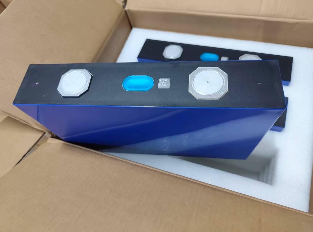
The 3.2V LiFePO4 cell is the foundational building block of the modern energy storage revolution. Every 12V, 24V, and 48V lithium battery bank used in solar installations, RVs, marine systems, and electric vehicles starts here — with individual cells, each operating at 3.2 volts nominal.
Understanding the 3.2V cell in depth isn't just academic. It directly determines what battery system you build, how you wire it, which cells you buy, how you charge it, and how long it will last. A buyer who understands the difference between a 280Ah and a 314Ah prismatic cell, knows how Grade A and Grade B cells differ, and can correctly wire a 16S configuration for a 48V system will build a system that performs as designed for 10–15 years. A buyer who doesn't risks costly mismatches, premature degradation, or outright system failure.
This guide gives you everything: the full voltage specification map, all cell formats with real dimensions and capacity ranges, the series/parallel wiring mathematics for every common system voltage, a grading and manufacturer selection framework, a correct charging protocol, and a complete application breakdown.
Part 1: What Is a 3.2V LiFePO4 Battery? — The Electrochemistry Behind the Voltage
A 3.2V LiFePO4 battery (also written as LFP, lithium iron phosphate, or Li-FePO4) is an individual rechargeable cell using lithium iron phosphate as the cathode material and graphite carbon as the anode, with a nominal cell voltage of 3.2 volts.
The 3.2V nominal voltage is not an arbitrary design choice — it is the thermodynamic consequence of the olivine crystal structure of LiFePO4. The electrochemical potential of the lithium iron phosphate cathode reaction (Fe³⁺/Fe²⁺ redox couple) fixes the equilibrium voltage at approximately 3.2–3.3V. This is lower than other lithium cathode chemistries (NMC at 3.6–3.7V, LCO at 3.6V) but produces the exceptionally flat discharge plateau that makes LFP uniquely useful in real-world applications.
Complete 3.2V LiFePO4 voltage specification map
| Parameter | Value | Notes |
|---|---|---|
| Nominal voltage | 3.2V | Thermodynamic midpoint of the discharge plateau |
| Fully charged voltage | 3.65V | Maximum charge cutoff; never exceed per cell |
| Nominal operating range | 3.0V–3.4V | Where ~80% of usable capacity is accessed |
| Discharge cutoff voltage | 2.5V | BMS hard cutoff to prevent over-discharge damage |
| Float/storage voltage | 3.2–3.3V | Resting OCV at ~50% SOC — ideal for storage |
| Self-discharge rate | 1–3% per month | At 25°C; lower at cooler temperatures |
| Thermal runaway onset | 250–350°C | vs. 150–250°C for NMC — significant safety margin |
Why the voltage matters for system design
The 3.2V nominal voltage governs every series/parallel calculation in a battery system. Unlike lead-acid (2V/cell) or NMC (3.7V/cell), LFP's 3.2V means that standard system voltages require specific cell counts:
- 12V nominal system: 4 cells × 3.2V = 12.8V (actual nominal)
- 24V nominal system: 8 cells × 3.2V = 25.6V
- 48V nominal system: 16 cells × 3.2V = 51.2V
The actual operating voltage of each system swings between the charge maximum and discharge minimum:
- A "12V" LFP bank is fully charged at 4 × 3.65V = 14.6V and fully discharged at 4 × 2.5V = 10V
- A "48V" LFP bank is fully charged at 16 × 3.65V = 58.4V and fully discharged at 16 × 2.5V = 40V
These actual voltage ranges must be matched to your inverter, charge controller, and BMS specifications — not just the nominal "12V" or "48V" label.
Part 2: All 3.2V LiFePO4 Cell Formats — Complete Breakdown with Dimensions
LiFePO4 cells at 3.2V nominal come in three fundamental physical formats: cylindrical, prismatic, and pouch. Each format has distinct characteristics that determine the right application.
Cylindrical LiFePO4 Cells
Cylindrical LFP cells use the same round form factor as standard AA or D-cell batteries, with cell chemistry determining voltage and capacity. The naming convention encodes dimensions: "18650" = 18mm diameter × 65mm length; "32700" = 32mm diameter × 70mm length.
Common cylindrical LFP sizes:
| Cell Model | Diameter × Length | Capacity Range | Nominal Voltage | Typical Use |
|---|---|---|---|---|
| IFR18650 | 18mm × 65mm | 1,500–2,000 mAh | 3.2V | Portable devices, power banks, DIY small packs |
| IFR26650 | 26mm × 65mm | 3,000–6,000 mAh | 3.2V | Power tools, flashlights, e-bikes |
| IFR32700 | 32mm × 70mm | 5,000–8,000 mAh | 3.2V | Light EVs, marine, van conversions, standby power |
| IFR38120 | 38mm × 120mm | 8,000–15,000 mAh | 3.2V | High-capacity DIY packs, UPS |
Cylindrical cell advantages: Mature manufacturing, consistent quality control, excellent internal pressure distribution (round geometry handles expansion well), widely available from multiple suppliers.
Cylindrical cell limitations: Low individual capacity means large cell counts for meaningful storage — a 12V/100Ah bank built from 32700 cells (≈6Ah each) requires approximately 67 cells minimum, plus all associated welding, connections, and sense wires. This complexity is why cylindrical cells are rarely the first choice for DIY home energy storage above a few hundred watt-hours.
Prismatic LiFePO4 Cells (Large-Format)
Large-format prismatic cells are the dominant format for home energy storage, RV/marine house banks, and commercial BESS applications. They are rectangular aluminum-cased cells with threaded M6 terminal posts, ranging from approximately 50Ah to over 340Ah capacity.
Key prismatic cell sizes in the 2025 market:
| Capacity | Nominal Voltage | Dimensions (approx.) | Weight (approx.) | Energy per Cell | Common Manufacturers |
|---|---|---|---|---|---|
| 100Ah | 3.2V | 173 × 117 × 45mm | ~1.8 kg | 0.32 kWh | CATL, EVE, CALB, GOTION |
| 200Ah | 3.2V | 173 × 207 × 45mm | ~3.4 kg | 0.64 kWh | EVE, CATL, CALB |
| 230Ah | 3.2V | 174 × 207 × 55mm | ~4.2 kg | 0.74 kWh | CATL, EVE |
| 280Ah | 3.2V | 173 × 207 × 72mm | ~5.5 kg | 0.90 kWh | EVE LF280K, CATL, CALB |
| 304Ah | 3.2V | 174 × 204 × 72mm | ~5.8 kg | 0.97 kWh | EVE LF304 |
| 314Ah | 3.2V | 174 × 207 × 72mm | ~6.0 kg | 1.00 kWh | EVE LF314, CATL CBC00, CALB |
The 280Ah and 314Ah cells are the current market workhorses for DIY solar and home storage. A 16-cell 48V/280Ah bank delivers 51.2V × 280Ah = ~14.3 kWh of nameplate capacity. The 314Ah cell offers approximately 12% more capacity in essentially the same physical footprint as the 280Ah, making it the better value per kWh for new builds.
Prismatic cell advantages: Exceptionally high capacity per cell drastically reduces cell count (16 cells for a 48V/280Ah system vs. potentially thousands of cylindrical cells for equivalent capacity), simple aluminum-bar bus connections, integral terminal posts, easier BMS wiring.
Prismatic cell limitations: Physical size requires structural compression and containment in the battery build; aluminum cases can suffer corner/edge damage if not properly supported; heavier per cell (though lighter per kWh than lead-acid).
Pouch LiFePO4 Cells
Pouch cells encase the electrode stack in a flexible laminated aluminum foil pouch rather than a rigid metal case. This format is used in some high-performance and custom applications.
Specifications: Nominally 3.2V; capacity varies widely by cell dimensions. Energy density can be higher than prismatic for the same footprint because there is no rigid case mass, but the soft case requires external mechanical compression to prevent swelling.
Best for: Custom battery packs for EVs and specialty applications where pack designers can engineer the compression structure. Less common in DIY and off-the-shelf residential storage due to the mechanical complexity.
Part 3: Series and Parallel Wiring — Building 12V, 24V, and 48V Systems from 3.2V Cells
This is the most practically critical section for anyone building a LiFePO4 battery bank. The mathematics are straightforward; the execution details are where most mistakes occur.
The two fundamental rules
Series connections increase voltage, capacity stays the same:
Connecting cells positive-to-negative in a chain adds their voltages. Four 3.2V/280Ah cells in series = 12.8V/280Ah.
Parallel connections increase capacity, voltage stays the same:
Connecting cells positive-to-positive and negative-to-negative adds their amp-hour ratings. Two 3.2V/280Ah cells in parallel = 3.2V/560Ah.
12V system: 4S configuration
| Configuration | Cells | System Voltage | Capacity | Total Energy |
|---|---|---|---|---|
| 4S1P (100Ah cells) | 4 | 12.8V nominal (14.6V full) | 100Ah | ~1.28 kWh |
| 4S1P (280Ah cells) | 4 | 12.8V nominal | 280Ah | ~3.58 kWh |
| 4S2P (280Ah cells) | 8 | 12.8V nominal | 560Ah | ~7.17 kWh |
Practical note: For most solar and RV applications requiring more than ~3 kWh, a 12V system becomes inefficient — high current demands at 12V require very large-gauge cabling. A 5,000W inverter at 12V draws approximately 417A; at 48V, the same 5,000W draws only about 100A. Systems above ~3 kWh should strongly consider 24V or 48V architecture.
24V system: 8S configuration
| Configuration | Cells | System Voltage | Capacity | Total Energy |
|---|---|---|---|---|
| 8S1P (100Ah cells) | 8 | 25.6V nominal (29.2V full) | 100Ah | ~2.56 kWh |
| 8S1P (280Ah cells) | 8 | 25.6V nominal | 280Ah | ~7.17 kWh |
| 8S2P (280Ah cells) | 16 | 25.6V nominal | 560Ah | ~14.34 kWh |
48V system: 16S configuration (recommended for most serious installations)
| Configuration | Cells | System Voltage | Capacity | Total Energy |
|---|---|---|---|---|
| 16S1P (100Ah cells) | 16 | 51.2V nominal (58.4V full) | 100Ah | ~5.12 kWh |
| 16S1P (280Ah cells) | 16 | 51.2V nominal | 280Ah | ~14.34 kWh |
| 16S1P (314Ah cells) | 16 | 51.2V nominal | 314Ah | ~16.08 kWh |
| 16S2P (314Ah cells) | 32 | 51.2V nominal | 628Ah | ~32.15 kWh |
48V is the recommended architecture for any system above ~5 kWh. Lower current for the same power means smaller, less expensive cabling; lower resistive losses; and better compatibility with the widest range of modern inverters and charge controllers.
Series vs. parallel wiring order: 4S2P vs. 2P4S
When building a pack with both series and parallel connections (e.g., 8 cells for a 12V/560Ah bank), the wiring order matters.
Series-first (4S then parallel — e.g., two 4S strings connected in parallel): Each string is internally balanced before parallel connection. Safer because the parallel connection only joins cells that are already at the same state of charge within their own string. Recommended for most DIY builds.
Parallel-first (2P then series — e.g., four pairs of parallel cells connected in series): Cells at the same position in the series string are paralleled first. Requires that all cells entering the parallel connection be at identical voltage — a tighter constraint.
Best practice: Use series-first (xSyP) topology, and ensure all cells are matched to within 10–20mV of each other before connecting. Always fully charge and individually balance cells before assembly into a pack.
Part 4: Cell Grade Selection — Grade A vs. Grade B vs. Grade C
This is the single most important purchasing decision most buyers make without enough information. Cell grade determines not just initial performance but long-term reliability and cycle life — and the distinction between grade A and grade B is not always obvious from marketing copy.
Understanding what cell grades actually mean
Cell grades (A, B, C) reflect capacity consistency and internal resistance relative to a manufacturer's own specification. This is a manufacturer-internal classification — there is no universal industry standard. A Grade A from one manufacturer may use different threshold criteria than Grade A from another.
That said, the practical differences are real:
| Grade | Capacity vs. Spec | Internal Resistance | Consistency Cell-to-Cell | Cycle Life | Best Use |
|---|---|---|---|---|---|
| Grade A | ≥100% of rated | At or below spec | Very high (±2–3%) | Full rated cycles (3,000–7,000+) | EV, solar, any critical system |
| Grade B | 90–99% of rated | Slightly above spec | Moderate (±5–8%) | Reduced (~80% of Grade A rating) | Budget backup, non-critical use |
| Grade C | Below 90% of rated | Significantly above spec | Low (high variability) | Substantially reduced | Prototyping, non-performance use only |
How to verify cell grade before purchasing
Request the datasheet and capacity test report: Grade A cells from legitimate manufacturers ship with QR codes linking to individual cell production data — voltage at shipment, capacity at test, internal resistance. If a supplier cannot provide this documentation, treat the cells as unverified.
Verify internal resistance: For a 280Ah prismatic LFP cell, Grade A internal resistance should be at or below approximately 0.18–0.25 mΩ (DC internal resistance). Cells measuring significantly above 0.35–0.4 mΩ are likely Grade B or below. Request DC internal resistance figures rather than AC (AC measurements, typically at 1kHz, tend to underestimate real internal resistance).
Check capacity at shipment SOC: Reputable suppliers ship prismatic cells at 30–50% SOC for safety. Measure open-circuit voltage on receipt — a cell at 30% SOC should read approximately 3.22–3.26V per cell for a healthy Grade A cell. Significant deviation from expected SOC at specified voltage indicates potential capacity issues.
Cell-to-cell voltage matching: For a batch of cells intended for a series pack, measure the OCV of every cell before assembly. Grade A cells from a single manufacturing batch should match within 5–10mV. Cells varying more than 20–30mV at the same measured SOC will create balancing challenges throughout the pack's life.
Look for certifications and QR codes: Grade A cells from established manufacturers (CATL, EVE, CALB, BYD, GOTION, Great Power) carry intact QR codes traceable to production records. Cells with missing, scratched, or replaced QR codes are a significant red flag.
Leading cell manufacturers (2025)
| Manufacturer | Headquarters | Notable Cells | Known For |
|---|---|---|---|
| CATL | Ningde, China | CBC00 314Ah, 280Ah, 100Ah | World's largest battery manufacturer; top quality control |
| EVE Energy | Huizhou, China | LF280K, LF304, LF314 | Popular for DIY/residential; widely available Grade A |
| CALB | Luoyang, China | CA100, CA300, L173 | Strong EV track record; robust thermal performance |
| BYD | Shenzhen, China | Blade cell, 302Ah | Pioneered blade cell format; vertically integrated |
| GOTION | Hefei, China | 105Ah, 340Ah | Growing export presence; competitive pricing |
| Great Power | Guangzhou, China | 100Ah, 135Ah | OEM for multiple branded battery products |
Part 5: Charging a 3.2V LiFePO4 Cell — The Correct Protocol
Every 3.2V LiFePO4 cell must be charged using the CC/CV (Constant Current/Constant Voltage) protocol with LFP-specific voltage parameters. Using a charger or charge controller configured for NMC (4.2V/cell) or lead-acid on LFP cells causes permanent damage.
The CC/CV charging stages
Stage 1 — Pre-charge (if deeply discharged below 2.8V/cell):
If any cell is below approximately 2.8V, apply a low pre-charge current (0.05C) until all cells reach 2.8V before applying full charge current. At voltages below 2.8V, cells are vulnerable to copper dissolution from the current collector if high current is applied.
Stage 2 — Constant Current (CC):
Apply the charge current (rated 0.2C–0.5C for longevity; maximum 1C for most Grade A cells) until cell voltage reaches 3.65V per cell. During this phase, voltage rises steadily. At 0.5C on a 280Ah cell, this means charging at 140A until the BMS detects 3.65V across the highest cell.
Stage 3 — Constant Voltage (CV):
Hold voltage steady at 3.65V per cell while current tapers exponentially. Continue until charging current drops to approximately 0.05C (5% of rated capacity in amps). For a 280Ah cell, charge termination occurs when current falls to approximately 14A.
Stage 4 — Charge termination:
Disconnect charge current. The battery rests at approximately 3.3–3.4V per cell after the surface charge dissipates (OCV will drop from 3.65V to resting OCV within a few minutes of disconnection).
System-level charge voltages for common configurations
| System Voltage | Cells in Series | Max Charge Voltage | Nominal Voltage | BMS Low Cutoff |
|---|---|---|---|---|
| 12V | 4S | 14.6V | 12.8V | 10.0V |
| 24V | 8S | 29.2V | 25.6V | 20.0V |
| 48V | 16S | 58.4V | 51.2V | 40.0V |
Critical charging rules
Rule 1 — LiFePO4-specific charger/controller required. Verify your solar charge controller, battery charger, and inverter/charger all have a LiFePO4 profile. The charge termination voltage for LFP (14.6V for 12V system) is meaningfully different from lead-acid (14.4–14.8V for AGM, but with different absorption behavior) and critically different from NMC (16.8V for a 12V-nominal 4S NMC pack). A lead-acid charger on LFP will typically undercharge (switches to absorption too early) and inconsistently top-balance; an NMC charger on LFP will overcharge and cause damage.
Rule 2 — No charging below 0°C. LFP cells must not receive charge current below freezing. Below 0°C, lithium ions cannot properly intercalate into the graphite anode, causing lithium plating that permanently reduces capacity. Use batteries with built-in BMS-controlled self-heating in cold climates.
Rule 3 — Protect with a properly configured BMS. The BMS must be programmed with cell-level overvoltage cutoff at 3.65V, under-voltage cutoff at 2.5V, and temperature-based charge inhibit below 0°C. These are not optional features — they are what prevents every single one of the common LFP failure modes.
Rule 4 — C-rate governs longevity. Charging at 0.2C–0.5C (56–140A for a 280Ah cell) rather than maximum rated 1C meaningfully extends cycle life by reducing thermal and mechanical stress on the electrodes per cycle. Size your solar array or charger to stay in the 0.2C–0.5C range for daily cycling.
Part 6: 3.2V vs. 3.7V Battery — The Complete Comparison
The most common question from buyers transitioning from consumer electronics familiarity: what is the difference between the 3.2V LFP chemistry and the 3.7V Li-ion chemistry found in phones, laptops, and drones?
| Parameter | 3.2V LiFePO4 | 3.7V NMC/LCO Li-ion |
|---|---|---|
| Cathode chemistry | Lithium iron phosphate (olivine) | NMC, NCA, LCO (layered oxide) |
| Nominal cell voltage | 3.2V | 3.6–3.7V |
| Full charge voltage | 3.65V | 4.2V |
| Discharge cutoff | 2.5V | 3.0V |
| Cycle life (to 80% SOH) | 3,000–7,000+ | 500–2,000 |
| Thermal runaway onset | 250–350°C | 150–250°C |
| Oxygen release at high temp | Minimal | Significant |
| Energy density | 90–160 Wh/kg | 150–270 Wh/kg |
| Cobalt content | None | Significant (NMC/NCA/LCO) |
| Best application fit | Energy storage, EVs, marine, solar | Consumer electronics, performance EVs |
| Replaceable 1:1? | No | No |
Can you substitute a 3.7V cell for a 3.2V cell?
No — and attempting to do so can cause serious problems. A device or system calibrated for 3.2V LFP uses that voltage range for BMS cutoffs, SOC estimation, and charge voltage calculation. Inserting a 3.7V NMC cell changes the full charge voltage (4.2V vs. 3.65V), discharge cutoff, and SOC curve. The existing BMS will behave incorrectly — likely overcharging the NMC cell above 3.65V (damaging it) or undercharging it. The voltage incompatibility is fundamental.
Part 7: Applications — Where 3.2V LiFePO4 Cells Are Used
Residential solar energy storage (the dominant application by volume)
The large-format prismatic 3.2V cell — particularly the 280Ah and 314Ah sizes from CATL and EVE — has become the standard cell for DIY and commercial residential energy storage systems. Sixteen cells in 16S form a 51.2V/280Ah bank (~14.3 kWh), which covers the average US household's daily consumption of 10–12 kWh with margin.
The cell-level economics are compelling: 16 EVE 314Ah Grade A cells at current 2025 pricing (~$70–90 per cell wholesale) build approximately 16 kWh of nameplate capacity for $1,100–1,450 in cells alone — well under $100/kWh at the cell level before BMS, enclosure, and cabling.
RV and marine house batteries
A 4S configuration of 100Ah or 280Ah prismatic cells replaces a lead-acid house bank with a system that weighs roughly half as much, delivers twice the usable capacity (95% DoD vs. 50%), and lasts 10–15 years vs. 3–5 years for quality AGM. For a 200Ah lead-acid bank (100Ah usable), a 4S1P 100Ah LFP pack weighs approximately 7 kg and delivers 95Ah usable — essentially matching the usable capacity in a package weighing about 25% as much.
Electric vehicles and light mobility
Cylindrical LFP cells (32700 in particular) are widely used in e-bikes, electric scooters, golf carts, and low-speed EVs. The 32700 cell (5,000–8,000 mAh, 3.2V) offers a good balance of capacity per cell and thermal performance for these applications. Larger EVs and electric buses predominantly use large-format prismatic cells from CATL, BYD, and CALB.
Off-grid cabins and remote power
For remote cabins and off-grid systems with no grid connection, 48V LFP banks built from prismatic cells have largely replaced the lead-acid and AGM banks that dominated the previous decade. The maintenance-free nature of LFP (no watering, no equalization charging, no corrosion management) is particularly valuable in unattended or remotely accessed installations.
Backup power and UPS systems
LFP's low self-discharge (1–3% per month) and ability to be stored at partial SOC without damage make it well-suited for backup and UPS applications. A 48V LFP bank in standby will retain most of its charge for 6–12 months without intervention — lead-acid requires monthly recharging to prevent sulfation in similar standby conditions.
Trolling motors and marine propulsion
The cylindrical 32700 and small prismatic cells are common in trolling motor applications. LFP delivers consistent voltage through the full discharge (unlike lead-acid, which produces progressively weaker motor performance as voltage drops), meaningful weight savings, and the ability to fully deplete without damage — all practically valuable features for a day on the water.
Part 8: How to Buy 3.2V LiFePO4 Cells — Practical Checklist
Before ordering:
- Specify Grade A cells from a named manufacturer (CATL, EVE, CALB, BYD, GOTION)
- Request the datasheet and confirm rated capacity, nominal voltage, and internal resistance specification
- Verify the seller can provide QR codes traceable to production data
- For large purchases, request a sample cell for independent testing before committing to full quantity
On receipt:
- Measure OCV of every cell before assembly — record results
- Verify cell-to-cell voltage spread is within 10–20mV for cells at the same stated SOC
- Inspect for physical damage: dents, scratches to terminal posts, case deformation
- Conduct a capacity test on representative cells if the application warrants it (full charge-discharge cycle at 0.2C, measure actual Ah delivered)
Red flags that indicate non-Grade-A cells:
- Missing, scratched, or replaced QR codes
- OCV spread greater than 50mV across a batch of cells at the same stated SOC
- Cells arriving significantly below the stated shipment SOC
- Internal resistance measurement noticeably above manufacturer spec
- Price significantly below market rate for the stated capacity and manufacturer
Frequently Asked Questions
What does 3.2V mean for a LiFePO4 battery?
3.2V is the nominal voltage of a single LiFePO4 cell — the average midpoint voltage during discharge under standard conditions. The cell actually operates between 2.5V (fully discharged cutoff) and 3.65V (fully charged). The 3.2V nominal is the thermodynamic result of the LiFePO4 olivine crystal structure's electrochemical potential, and it is lower than NMC (3.6–3.7V) or LCO (3.6V) chemistries. Multiple cells are connected in series to reach practical system voltages: 4 cells = 12.8V (nominal "12V"), 16 cells = 51.2V (nominal "48V").
How many 3.2V LiFePO4 cells do I need for a 12V, 24V, or 48V system?
Exactly 4 cells in series for a 12V system (12.8V nominal), 8 cells for a 24V system (25.6V nominal), and 16 cells for a 48V system (51.2V nominal). To increase capacity (Ah) without changing voltage, add cells or complete strings in parallel. For example, two 4S strings of 280Ah cells connected in parallel creates a 12.8V/560Ah bank.
What is the difference between Grade A and Grade B LiFePO4 cells?
Grade A cells meet or exceed the manufacturer's rated capacity specification with low internal resistance and high consistency cell-to-cell. Grade B cells fall slightly below rated capacity (typically 90–99% of spec) with somewhat higher internal resistance and more cell-to-cell variability. In practical terms, Grade A cells deliver more usable energy, last more cycles before reaching 80% state of health, and create fewer balancing challenges in series packs. For any serious solar, EV, or marine application, Grade A cells from a named manufacturer are the correct choice.
Can I charge a 3.2V LiFePO4 battery with a regular lithium charger?
Only if the charger is specifically configured for LiFePO4 chemistry. Standard lithium-ion chargers (designed for NMC/LCO at 4.2V/cell) will overcharge LFP cells — the 4.2V/cell NMC target is far above LFP's 3.65V/cell maximum and causes immediate, permanent damage. Lead-acid chargers typically undercharge LFP (switching to float too early) and won't properly top-balance the cells. Always verify LiFePO4-specific charge profiles in any charger, inverter-charger, or solar charge controller connected to an LFP bank.
How long do 3.2V LiFePO4 batteries last?
High-quality Grade A LFP cells in properly managed systems last 3,000–7,000+ full charge-discharge cycles before capacity falls to 80% of rated (the industry-standard end-of-first-life threshold). Cycled once daily, 3,000 cycles is 8.2 years; 6,000 cycles is 16.4 years. Calendar life is typically 10–15 years at moderate temperatures. The CATL CBC00 314Ah cell carries a specification of more than 7,000 cycles, corresponding to over 19 years of daily cycling.
Is 3.2V LiFePO4 safer than 3.7V lithium-ion?
Yes — significantly. The olivine crystal structure of LiFePO4 is fundamentally more thermally stable than the layered oxide structures of NMC or LCO. LFP's thermal runaway onset temperature is 250–350°C versus 150–250°C for NMC — roughly a 100°C safety margin. LFP cathodes release minimal oxygen even at elevated temperatures, making self-sustaining combustion much harder to establish. For enclosed applications (residential, marine, RV), LFP's intrinsic safety advantage is one of its most important practical attributes.
Conclusion
The 3.2V LiFePO4 cell is the building block of the most durable, safest, and increasingly cost-effective energy storage technology available today. Understanding it at the cell level — voltage parameters, physical formats, series/parallel configurations, grade selection, and charging protocol — enables you to design and build systems that perform as engineered for a decade or more.
The practical summary: use Grade A cells from named manufacturers (CATL, EVE, CALB); build 48V/16S for any system above ~5 kWh; stay within 0.2C–0.5C charge rates for longevity; verify every cell on receipt; charge only with LFP-configured equipment; and let a properly configured BMS handle cell-level protection.
Get these fundamentals right and a 3.2V LFP battery bank is among the most reliable long-term investments in modern energy infrastructure.
- Next:What Is the Fire Temperature Range of Lithium-Ion Batteries
- Previous:Understanding the Different Types of LiFePO4 Batteries
Contact Details
Lithium LiFePO4 Batteries and Lithium LiFePO4 Cells Supplier - LiFePO4 Battery Shop
Contact Person: Miss. Elena Wang
WhatsApp : +8615263269227
Skype : +8615263269227
WeChat :15263269227
Email : info@lifepo4batteryshop.com
All Products
- TC Elcon Charger (0)
- Headway Lithium Battery (6)
- Blade Battery (10)
- Semi Solid State Battery (6)
- A123 Battery (6)
- Sinopoly Battery (7)
- GBS Battery (16)
- CALB Battery (25)
- Cylindrical Cell (10)
- Energy Storage System (0)
- Battery Management System (15)
- Sodium ion Battery Cell (4)
- Lithium Titanate Battery (22)
- Ternary Lithium Battery Cell (12)
- REPT Battery (10)
- BYD Battery (5)
- CATL Battery (15)
- Thunder Sky Winston Battery (26)
- EVE Battery (35)
- LiFePO4 Battery Cell (24)
Certification
Customer Reviews
- I have fond memories of our meeting in Shanghai with LiFePO4 Battery Shop Elena. Your company left a strong impression on me with its impressive growth and professionalism. We both value straightforwardness and honesty, which I believe are the most important qualities in any partnership. I am confident that we can build a successful collaboration based on these shared values. —— Robert from USA
- I've been working with LiFePO4 Battery Shop for years, and their reliability is unmatched. While other suppliers frequently change sales teams, LiFePO4 Battery Shop has consistently provided exceptional service with a stable team. Their commitment to quality and customer support truly sets them apart. —— Henry from Australia