Blog
How to Configure 3.2V LiFePO4 Cells to Build 12V, 24V & 48V Battery Packs: The Complete DIY Guide
2026-05-14 | Calvin
Building your own LiFePO4 battery pack is one of the most rewarding DIY energy projects you can take on — but only if you understand the cell configurations before you touch a single busbar. This guide covers:
- The exact series and parallel configurations needed for 12V, 24V, and 48V systems
- The difference between series-first (4S2P) and parallel-first (2P4S) wiring — and when to use each
- BMS selection criteria for each voltage tier
- Physical layout strategies for safety and performance
- Common wiring mistakes that destroy cells (and how to avoid them)
Whether you're building a DIY solar storage system, powering an RV, or running an off-grid cabin, this guide gives you everything you need to get it right the first time.
Why 3.2V LiFePO4 Cells? A Quick Primer
Each prismatic LiFePO4 cell has a nominal voltage of 3.2V, a full-charge voltage of 3.65V, and a minimum discharge voltage of 2.5V. This flat voltage curve is one of the key advantages of LiFePO4 chemistry — it delivers steady power across most of its discharge range.
Because 3.2V doesn't match any common system voltage on its own, you need to connect cells in series to raise voltage, and in parallel to raise capacity (Ah). The two connection methods can also be combined.
Core Rules to Remember:
- Series connection → adds voltages together, capacity stays the same
- Parallel connection → adds capacities (Ah) together, voltage stays the same
- Series-Parallel (SP) or Parallel-Series (PS) → increases both voltage and capacity
Voltage Reference Table: How Many Cells Do You Need?
| System Voltage | Cells in Series | Nominal Voltage | Operational Range | Use Case |
|---|---|---|---|---|
| 12V | 4S | 12.8V | 10V – 14.6V | RV, Marine, Small Solar |
| 24V | 8S | 25.6V | 20V – 29.2V | Mid-size Solar, E-Bikes |
| 48V (true) | 15S | 48.0V | 37.5V – 54.75V | Inverters, Off-grid |
| 48V (recommended) | 16S | 51.2V | 40V – 58.4V | Powerwall, Large Solar |
Pro Tip: A 16S (51.2V) pack is almost always the better choice over 15S (48V). You get ~6.5% more energy per cell and better compatibility with 48V inverters like Victron, Deye, or Growatt, which are actually rated for 51.2V nominal input.
12V (12.8V) LiFePO4 Cell Configurations
To reach a nominal 12V, you need 4 cells in series (4S). This is the most common configuration for RV house batteries, marine applications, and small solar setups.
4S1P — The Baseline 12V Pack
Configuration: 4 cells in series, 1 parallel group
Result: 12.8V at whatever Ah rating your cells have
This is the simplest 12V build. Four cells are connected positive-to-negative in a chain. The pack voltage equals 4 × 3.2V = 12.8V. Capacity equals a single cell's capacity.
Example: 4 × 280Ah cells in 4S1P = 12.8V 280Ah = 3.58 kWh
Best physical layout: Straight line (cells in a row, all oriented the same direction). The terminals of the finished pack end up as far apart as possible, reducing the chance of accidental shorts.
8-Cell 12V Configurations: 4S2P vs. 2P4S
When you want to double the capacity of a 12V pack, you use 8 cells. Here is where the critical question arises: series-first (4S2P) or parallel-first (2P4S)?
Option A: 4S2P (Series-First)
Wire each group of 4 cells in series first to make two 12.8V strings, then connect those two strings in parallel.
Result: 12.8V, Ah = 2 × single cell Ah
Advantages:
- Each series string acts independently until the final parallel connection
- Easier to pre-balance individual strings before connecting
- If one cell fails, you can diagnose which string is the problem
Disadvantages:
- Requires more careful attention when joining the two strings (voltage must match before connecting in parallel)
- BMS must handle current from both parallel strings
Option B: 2P4S (Parallel-First) ← Recommended
Wire each pair of cells in parallel first (two cells side-by-side at each position), then connect the four parallel groups in series.
Result: 12.8V, Ah = 2 × single cell Ah (identical to 4S2P)
Why parallel-first is often preferred by experienced builders:
- Cells are balanced within each parallel group before any series voltage stress
- Busbar lengths stay shorter, reducing voltage drop across busbars
- Easier to maintain physical cell compression with a symmetric layout
- The BMS sees the pack as a simple 4S string — simpler wiring
Example: 8 × 280Ah cells in 2P4S = 12.8V 560Ah = 7.17 kWh
Expert Note: The series-first vs. parallel-first debate has no universally right answer. It depends on cell quality matching, your BMS, and your physical enclosure design. If your cells are well-matched (within 5mV of each other and within 1% of stated Ah), parallel-first works excellently. For mixed-age or mismatched cells, series-first gives you more control.
24V (25.6V) LiFePO4 Cell Configurations
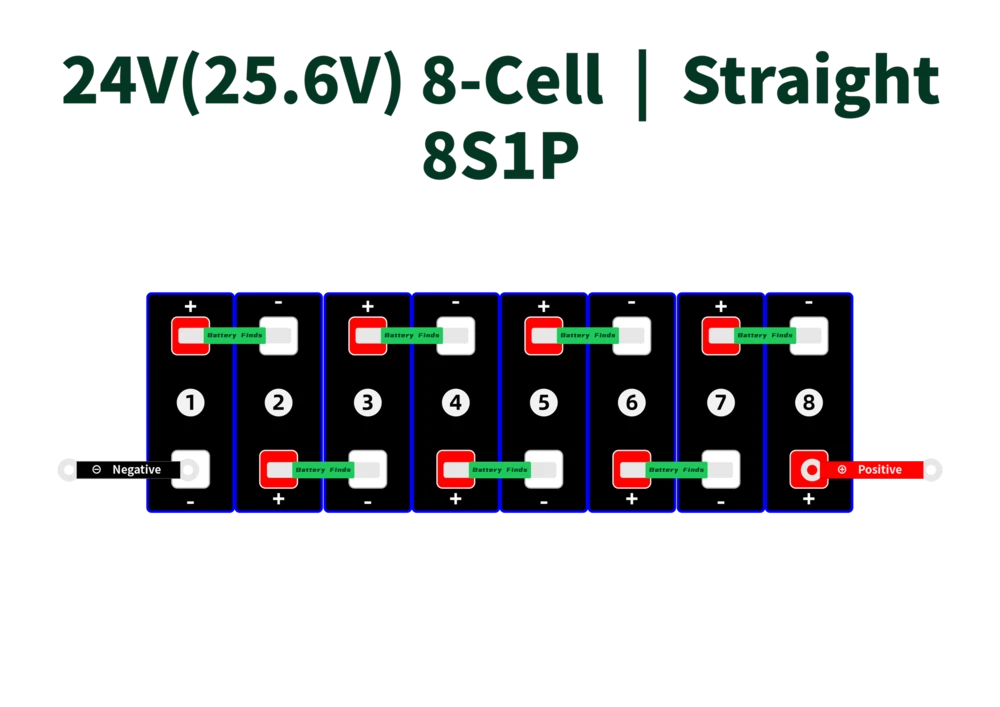
To reach 24V nominal, you need 8 cells in series (8S).
8S1P — The Baseline 24V Pack
Configuration: 8 cells in series
Result: 25.6V at single-cell capacity
Example: 8 × 280Ah cells = 25.6V 280Ah = 7.17 kWh
24V systems are popular for mid-size solar arrays, electric bicycles with large battery packs, and as the building block for 48V systems.
16-Cell 24V Configurations: 8S2P vs. 2P8S
Identical logic to the 12V builds: you can go series-first (8S2P) or parallel-first (2P8S).
8S2P (Series-First)
Build two independent 8S strings at 25.6V each, then join them in parallel.
2P8S (Parallel-First) ← Recommended for large cells
At 24V, cells are physically larger (typically 280Ah to 314Ah prismatic cells are big). The 2P8S layout allows you to keep busbars short and symmetric, which matters especially with the high current these large cells can deliver.
Example: 16 × 280Ah cells in 2P8S = 25.6V 560Ah = 14.34 kWh
Physical layout options for 16-cell 24V packs:
- Block (2×8 grid): Compact, good for square enclosures
- Straight (1×16 line): Best for long, narrow enclosures (like under RV slides)
- Long double row: Two rows of 8, good for standard battery boxes
48V LiFePO4 Cell Configurations — The Power Tier
48V is the dominant voltage for serious off-grid solar systems, whole-home backup, and high-powered inverters. It's also where most experienced builders end up.
Why 48V over 12V or 24V?
Higher voltage = lower current for the same power. A 5,000W load at:
- 12V requires 417A → enormous cables, massive heat, complex BMS
- 24V requires 208A → still heavy wiring
- 48V requires only 104A → manageable cables, less heat, safer
This is why professional solar installers almost universally use 48V systems for anything above 3kW.
15S vs. 16S: Which 48V Pack Should You Build?
| 15S (48V) | 16S (51.2V) | |
|---|---|---|
| Cells in series | 15 | 16 |
| Nominal voltage | 48.0V | 51.2V |
| Full charge voltage | 54.75V | 58.4V |
| Energy (per 280Ah cell) | 13.44 kWh | 14.34 kWh |
| Inverter compatibility | Limited | Wide (Victron, Growatt, Deye, etc.) |
| BMS availability | Limited | Abundant |
| Recommended? | No | Yes |
The verdict: Build 16S. The extra cell costs a fraction more, but gives you 6.5% more energy, far better inverter compatibility, and a much larger selection of BMS units designed for 16S packs.
16S1P — The Standard 48V DIY Pack
Configuration: 16 cells in series
Result: 51.2V at single-cell Ah capacity
Example: 16 × 280Ah cells = 51.2V 280Ah = 14.34 kWh
Example: 16 × 304Ah cells = 51.2V 304Ah = 15.56 kWh
Example: 16 × 314Ah cells = 51.2V 314Ah = 16.08 kWh
This is the standard Powerwall-style build. One BMS, one pack, clean wiring.
Physical layout options:
- Block (4×4 grid): The most compact layout. Good for cube-shaped enclosures
- Straight (1×16 line): Long but very safe — terminals end up at opposite ends
- 2×8 double row: Popular for custom plywood/aluminum battery boxes
32-Cell 48V Configurations: 16S2P vs. 2P16S
This is the big build — 32 large prismatic cells creating 28+ kWh in a single pack.
16S2P (Series-First)
Build two complete 16S strings at 51.2V each, then join them in parallel.
Best for: Builders who want to test and balance each string independently before connecting. Also better if cells are from different batches or have slightly different internal resistance.
Critical warning: When connecting two 16S strings in parallel, they MUST be within 0.1V of each other before connecting. Use a multimeter. Connect through a pre-charge resistor if possible to prevent high inrush current.
2P16S (Parallel-First) ← Recommended for matched cells
Group cells in pairs first, then connect 16 parallel pairs in series.
Best for: Well-matched cells bought in the same batch. Keeps busbar runs short and symmetric. The BMS sees a clean 16S configuration.
Example: 32 × 280Ah cells in 2P16S = 51.2V 560Ah = 28.67 kWh
Example use case: Whole-home backup for a 3-bedroom house running for 2+ days without solar input.
BMS Selection Guide for Each Configuration
The Battery Management System (BMS) is the brain and guardian of your pack. Choosing the wrong one is the #1 mistake DIY builders make.
12V System BMS (4S)
- Recommended voltage: 4S, rated for 12.8V
- Current rating: Size for your peak load. For a 3000W inverter: 3000W ÷ 12V = 250A peak. Use a 250A–300A BMS.
- Popular choices: Daly 4S, JK BMS 4S, ANT BMS 4S
- Active balancing recommended? Yes, for packs above 200Ah
24V System BMS (8S)
- Recommended voltage: 8S, rated for 25.6V
- Current rating: For a 3000W inverter: 3000W ÷ 24V = 125A. Use 150A–200A BMS.
- Popular choices: Daly 8S, JK BMS 8S
48V System BMS (16S)
- Recommended voltage: 16S, rated for 51.2V
- Current rating: For a 5000W inverter: 5000W ÷ 48V ≈ 104A. Use a 150A–200A BMS.
- For large 32-cell builds: Either use one 16S BMS with dual-string parallel output, or use a BMS designed for 2P configurations
- Popular choices: JK BMS 16S Active Balancer, Daly 16S Smart BMS, JKBMS with CAN/RS485 for Victron integration
BMS Tip for Inverter Integration: If you're connecting to a Victron Multiplus, Growatt, or Deye inverter, choose a BMS with CAN bus or RS485 communication. This allows the inverter to read state-of-charge (SoC), cell voltages, and temperature data directly from the BMS — enabling much smarter charge/discharge management.
Busbar Sizing and Physical Layout Best Practices
Busbar Current Capacity
Busbars carry the full current your pack can deliver. Undersized busbars create heat and resistance, degrading both performance and safety.
| Pack Voltage | Typical Peak Current | Minimum Busbar Cross-Section |
|---|---|---|
| 12V 4S | 200–300A | 50mm² copper or 80mm² aluminum |
| 24V 8S | 100–150A | 35mm² copper or 50mm² aluminum |
| 48V 16S | 80–120A | 25mm² copper or 35mm² aluminum |
Factory busbars that ship with prismatic cells are sized for series connections only. For parallel configurations (2P builds), you need heavier busbars — at minimum, double the thickness of the factory bars, or purchase dedicated heavy-duty parallel busbars.
Busbar Length and Voltage Drop
In parallel configurations, long busbars spanning multiple cells create small but meaningful voltage differences between cells at each end of the busbar. Because the LiFePO4 voltage curve is so flat, even a 5–10mV difference can cause cells to drift over hundreds of cycles.
Best practice: Keep parallel busbars as short as possible. If spanning more than two posts, use a single multi-hole busbar rather than chaining two-hole busbars — the inter-busbar connection point adds more resistance than the busbar itself.
The Straight Layout: Why It's Safest
The straight (single-row) layout places all cells in a line with alternating terminal orientations. The pack's final positive terminal ends up at one end, the final negative at the other. This maximizes the physical distance between the two main terminals, reducing the risk of accidental short circuits during assembly and maintenance.
The block (grid) layout is more compact but puts the main terminals in closer proximity. Always use a main fuse or breaker between the pack and the load when using block configurations.
Cell Matching: The Step Most Builders Skip
Before connecting any cells, you must verify they are matched. Mismatched cells in series will cause the weakest cell to hit cutoff voltage first on discharge and overcharge voltage first on charge. This shortens the life of that cell dramatically, and soon the whole pack.
Matching checklist before assembly:
- Voltage match: All cells within 5mV of each other (ideally within 2mV)
- Capacity match: Capacity test each cell. Group cells within 1–2% of rated Ah together
- Internal resistance match: Measure with a battery tester. Match cells within 0.1mΩ of each other for parallel connections
- Same batch: Cells from the same manufacturing batch are the most naturally matched
- Temperature: Let all cells reach room temperature before measuring or connecting
Top-balancing before first use: Before sealing your pack, connect all cells in parallel for 24–48 hours to allow them to reach the same voltage. Then disconnect and assemble in your final configuration. This is called top-balancing and it significantly improves long-term cell health.
Use Case Guide: Which Configuration Is Right for You?
| Application | Recommended Configuration | Example Build |
|---|---|---|
| RV house battery (small) | 4S1P | 4 × 100Ah = 12.8V 100Ah (1.28 kWh) |
| RV house battery (large) | 4S2P or 2P4S | 8 × 280Ah = 12.8V 560Ah (7.17 kWh) |
| Off-grid cabin, small | 16S1P | 16 × 280Ah = 51.2V 280Ah (14.34 kWh) |
| Off-grid cabin, large | 16S2P or 2P16S | 32 × 280Ah = 51.2V 560Ah (28.67 kWh) |
| Powerwall / home backup | 16S1P | 16 × 314Ah = 51.2V 314Ah (16.08 kWh) |
| Marine trolling motor | 4S1P | 4 × 100Ah = 12.8V (replaces 12V group 27) |
| E-bike / EV conversion | 8S or 16S custom | Based on motor controller voltage |
| Grid-tied solar buffer | 16S1P or 2P16S | With Victron/Deye inverter + CAN BMS |
Safety Checklist Before Powering Up
Before connecting your pack to any load or charger, run through this list:
- [ ] All cell voltages within 5mV of each other
- [ ] All busbars torqued to manufacturer spec (typically 4–6 Nm for M6 terminals)
- [ ] BMS wiring harness connected in correct order (B- first on most BMS units)
- [ ] Main fuse or breaker sized correctly between pack and load
- [ ] Pack enclosure provides compression (1–2 PSI on prismatic cells recommended)
- [ ] Temperature sensor from BMS touching cells (not just the air inside the box)
- [ ] All connections checked with a multimeter before closing the enclosure
- [ ] Charge/discharge cutoff voltages programmed correctly into BMS
Frequently Asked Questions
Can I mix cell brands in the same pack?
No. Different brands use different cell chemistry formulations, resulting in different internal resistance and capacity curves. Even if they share the same nominal specs, they will drift apart over time. Stick to a single brand and ideally a single batch.
Can I add more cells to an existing pack?
Adding cells in parallel to an existing pack is possible only if the new cells are top-balanced to match the existing pack voltage first. Adding cells to expand a series string is not recommended — it changes the pack voltage and renders the existing BMS incompatible.
My cells arrived at 3.3V. Is that normal?
Yes. Cells are shipped at a partial state of charge (typically 30–50%) for transport safety. 3.3V on a LiFePO4 cell is normal and represents roughly 30–40% SoC. Top-balance them before first assembly.
How many charge cycles will my DIY pack last?
Quality Grade A LiFePO4 cells (CATL, EVE, Lishen) are rated for 3,000–6,000 cycles to 80% capacity. If you charge/discharge once per day, that's 8–16 years of useful life. The BMS is often the component that fails first — invest in quality there.
Is 4S2P or 2P4S better?
For well-matched cells from the same batch: 2P4S (parallel-first). For cells of different ages or from different batches: 4S2P (series-first) so you can monitor each series string independently.
- Next:Spot Welding vs. Soldering Lithium Batteries: Which Method Should You Use?
- Previous:AGM Battery Pros and Cons: A Complete Guide for 2026
Contact Details
Lithium LiFePO4 Batteries and Lithium LiFePO4 Cells Supplier - LiFePO4 Battery Shop
Contact Person: Miss. Elena Wang
WhatsApp : +8615263269227
Skype : +8615263269227
WeChat :15263269227
Email : info@lifepo4batteryshop.com
All Products
- TC Elcon Charger (0)
- Headway Lithium Battery (6)
- Blade Battery (10)
- Semi Solid State Battery (6)
- A123 Battery (6)
- Sinopoly Battery (7)
- GBS Battery (16)
- CALB Battery (25)
- Cylindrical Cell (9)
- Energy Storage System (0)
- Battery Management System (15)
- Sodium ion Battery Cell (4)
- Lithium Titanate Battery (22)
- Ternary Lithium Battery Cell (12)
- REPT Battery (10)
- BYD Battery (5)
- CATL Battery (15)
- Thunder Sky Winston Battery (26)
- EVE Battery (35)
- LiFePO4 Battery Cell (18)
Certification
Customer Reviews
- I have fond memories of our meeting in Shanghai with LiFePO4 Battery Shop Elena. Your company left a strong impression on me with its impressive growth and professionalism. We both value straightforwardness and honesty, which I believe are the most important qualities in any partnership. I am confident that we can build a successful collaboration based on these shared values. —— Robert from USA
- I've been working with LiFePO4 Battery Shop for years, and their reliability is unmatched. While other suppliers frequently change sales teams, LiFePO4 Battery Shop has consistently provided exceptional service with a stable team. Their commitment to quality and customer support truly sets them apart. —— Henry from Australia