
Blog
DIY LiFePO4 Car Battery Guide: Can You Build One Safely?
2026-09-04 | Calvin
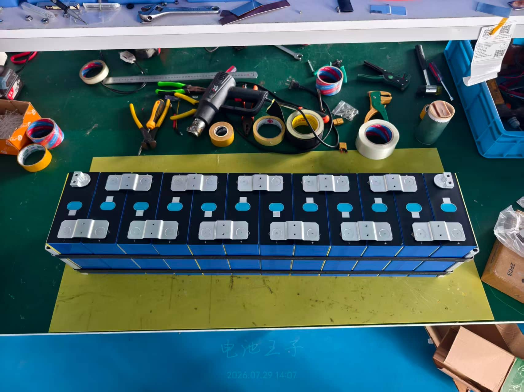
A DIY LiFePO4 car battery can reduce weight and provide strong starting performance, but it is not simply a four cell battery pack placed inside a box. A starter battery must deliver several hundred amps, tolerate heat and vibration, work with the vehicle charging system, survive electrical transients, and remain dependable when the engine is cold.
This guide explains how to evaluate a LiFePO4 starter battery project, select the right components, plan the pack, and test it before installation. It is written for educational purposes. Vehicle electrical systems vary, so confirm every limit against the vehicle service information, cell data sheets, BMS documentation, and local requirements.
Quick Answer
A conventional 12 volt car usually needs four LiFePO4 cells connected in series, creating a battery with a nominal voltage near 12.8 volts. That voltage alone does not make the pack suitable for engine starting.
A safe design also needs:
- Cells designed to supply the required cranking current
- A BMS or protection system that can carry the starter surge without disconnecting
- Compatibility with the alternator, voltage regulator, and vehicle energy management system
- Low temperature charging protection
- Automotive grade connections, insulation, containment, and mounting
- Protection against short circuits, overvoltage, undervoltage, heat, and electrical transients
- Bench testing under realistic load before installation
If the car has automatic start stop, regenerative charging, a smart alternator, an intelligent battery sensor, battery registration, or safety critical 12 volt loads, a purpose built and vehicle approved starter battery is usually the better choice.
LiFePO4 Starter Battery vs Deep Cycle Battery
The first design decision is understanding what a starter battery must do.
A deep cycle battery supplies moderate current for a long period. It is commonly used for solar storage, RV equipment, marine house loads, and backup power. A starter battery supplies an extremely high current for a few seconds, then receives charge from the alternator.
These jobs require different cell characteristics and protection strategies. A deep cycle LiFePO4 battery may have enough stored energy to start an engine, yet its cells, BMS, terminals, or internal connections may not be rated for the required surge.
| Requirement | Starter battery | Deep cycle battery |
|---|---|---|
| Main purpose | Deliver very high current for engine cranking | Supply energy over a longer period |
| Important rating | Cranking current and voltage under load | Amp hour capacity and cycle life |
| Typical discharge pattern | Short and intense | Longer and more controlled |
| Protection challenge | Allow starting surge without unsafe disconnects | Control sustained charge and discharge current |
| Vehicle compatibility | Critical | Application dependent |
Do not convert amp hour capacity into cold cranking amps with a simple formula. The relationship depends on cell chemistry, internal resistance, temperature, construction, connection resistance, and the test method. Compare a proposed pack with the original battery using verified cranking data under the same standard.
Should You Build a DIY LiFePO4 Car Battery?
A DIY build is most realistic for a simple vehicle with well documented electrical requirements, generous access to the battery compartment, predictable temperatures, and no battery coding requirement. Race vehicles and specialist projects may also justify the effort when weight reduction matters and the electrical system has been designed around the battery.
A DIY build may be reasonable when
- You can obtain complete cell and BMS data sheets
- You can measure starter current and charging voltage
- You understand high current DC design and can make verified low resistance connections
- You can test the finished pack away from the vehicle
- The vehicle manufacturer does not prohibit the chemistry change
- The charging system remains within the battery limits in every operating mode
- You accept that a homemade pack may affect warranty, insurance, inspection, and transport
Buy a purpose built starter battery when
- The vehicle uses automatic start stop or regenerative charging
- The battery must be registered or coded after replacement
- The car has an intelligent battery sensor or adaptive alternator control
- The vehicle is used in freezing weather
- The 12 volt battery supports steering, braking, driver assistance, security, or other critical electronics
- You cannot confirm the starter surge, alternator behavior, and protection requirements
- The car must remain dependable for daily transport
Modern vehicles can adjust charging according to battery type, capacity, age, and state of charge. VARTA notes that an incorrectly registered replacement can prevent the battery management system from using the correct algorithm and can interfere with automatic start stop operation.
Record the Vehicle Requirements First
Do not choose cells before documenting what the car expects from its battery.
| Item to record | Why it matters | Where to check |
|---|---|---|
| Nominal electrical system voltage | Determines the series cell count and equipment compatibility | Service manual and original battery label |
| Original battery technology | Shows the charging strategy the vehicle was designed to use | Battery label, parts catalog, and service information |
| Cold cranking rating | Provides a starting performance target | Original battery label and vehicle manual |
| Battery capacity | Affects parked loads, reserve time, and vehicle energy management | Original battery label |
| Starter current | Sets the real peak current requirement | Automotive current clamp during hot and cold starts |
| Maximum charging voltage | Must remain below the pack and BMS limits | Logged measurement across normal operating conditions |
| Alternator current capability | A lithium pack can accept current quickly and may stress an unsuitable charging system | Alternator data and service manual |
| Parasitic load | Determines how long the car can remain parked | Sleep current test after vehicle modules shut down |
| Battery size and terminal layout | Determines enclosure fit, retention, cable reach, and polarity | Battery tray and original battery |
| Temperature range | Affects starting power, charging permission, and cell life | Climate data and under hood measurements |
| Battery registration requirement | May prevent a chemistry change or require diagnostic programming | Vehicle service information and diagnostic documentation |
Basic 12 Volt LiFePO4 Battery Architecture
A LiFePO4 cell has a nominal voltage near 3.2 volts. Four cells in series create a nominal 12.8 volt pack. This arrangement is commonly described as 4S.
Series connection increases voltage while amp hour capacity remains the same. Parallel connection increases capacity and current capability while voltage remains the same.
Example using four cells
- Cell nominal voltage: 3.2 volts
- Cell capacity: 40 amp hours
- Configuration: four cells in series
- Pack nominal voltage: 12.8 volts
- Pack nominal capacity: 40 amp hours
- Pack nominal energy: 512 watt hours
The calculation is:
12.8 volts × 40 amp hours = 512 watt hours
This energy calculation says nothing about starting ability. The cells must also deliver the required current without excessive voltage drop, heat, or damage.
Why a 4S pack is not automatically a direct replacement
The voltage ranges of a four cell LiFePO4 pack and a conventional 12 volt vehicle overlap, but the charging behavior is different. LiFePO4 voltage changes relatively little through much of its state of charge. A vehicle algorithm developed for lead acid, AGM, or EFB may therefore estimate state of charge incorrectly or apply unsuitable charging behavior.
The pack must also tolerate electrical events that do not occur in a simple bench power system. ISO 7637 Part 2 covers conducted electrical transients in 12 volt and 24 volt road vehicles, while ISO 16750 Part 2 addresses electrical loads and environmental stresses for road vehicle electrical equipment. These standards show why resting voltage alone is not a complete compatibility test.
Components Required for a DIY LiFePO4 Starter Battery
| Component | Selection requirement |
|---|---|
| LiFePO4 cells | Matched cells with verified high current discharge data and suitable temperature limits |
| Battery management system | Correct series count, charging limits, balancing, temperature sensing, and proven starter surge capability |
| Busbars or cell interconnects | Low resistance conductors rated for continuous and cranking current |
| Automotive terminals | Correct polarity, size, mechanical strength, and current capability |
| Main protection | Equipment chosen for the conductor, battery fault current, and vehicle architecture |
| Enclosure | Rigid, insulated, heat resistant, vibration resistant, and securely retained |
| Cell restraints | Designed for the selected cell type and manufacturer requirements |
| Insulation barriers | Protect cell bodies, terminals, interconnects, and enclosure surfaces from contact |
| Temperature sensors | Placed where they can detect cell temperature accurately |
| Monitoring connection | Optional, but useful for pack voltage, cell voltage, current, temperature, and fault history |
Use cells from one model, one production batch when possible, and one documented history. Do not mix new and used cells, different capacities, or different internal constructions in the same starter pack.
How to Choose Cells for Engine Starting
Cell capacity is only one part of selection. A starter battery requires low internal resistance and verified pulse performance.
Check these cell specifications
- Nominal capacity
- Maximum continuous discharge current
- Maximum pulse current
- Permitted pulse duration
- Voltage drop at high current
- DC internal resistance
- Charge voltage range
- Maximum charge current
- Charging and discharging temperature limits
- Terminal torque and connection requirements
- Mechanical restraint or compression requirements
Do not confuse CCA, CA, and amp hours
Cold cranking amps, cranking amps, and amp hours describe different performance characteristics. Ratings also depend on the test standard. Compare values only when the temperature, duration, voltage threshold, and standard are stated.
The original battery rating remains the safest starting target. A lower capacity lithium pack may crank strongly when warm, yet provide too little reserve for alarms, telematics, lighting, control modules, or repeated start attempts.
Purpose built automotive lithium batteries show how different the ratings can be. One commercial H7 LiFePO4 starter battery is offered with actual capacities from 40 to 80 amp hours and cranking ratings from 1,500 to about 2,000 amps, together with a complete BMS. These figures are product specific, but they demonstrate why capacity and cranking output must be evaluated separately.
BMS Requirements for a LiFePO4 Car Battery
A general deep cycle BMS may disconnect during engine cranking. A starter battery protection system must be designed around very high current and the consequences of disconnection.
Minimum functions to evaluate
- Cell overvoltage protection
- Cell undervoltage protection
- Short circuit and overcurrent protection
- High temperature protection
- Low temperature charge blocking
- Cell balancing
- Starter surge current and duration
- Continuous current for vehicle loads
- Recovery behavior after a protection event
- Resistance and heat at the required current
Why BMS disconnect behavior matters
If a BMS opens while the starter is engaged, the car will not start. If it opens while the alternator is charging, the sudden loss of the battery can create a serious electrical event. The alternator, regulator, and sensitive electronics must be considered as one system.
A DIY builder should not assume that a printed peak rating proves starter suitability. Confirm the test duration, temperature, state of charge, cooling conditions, switch technology, connection resistance, and recovery behavior.
Commercial starter batteries commonly integrate overcharge, over discharge, thermal, short circuit, and balancing functions. That integrated approach is a useful benchmark when evaluating a DIY design.
Alternator and Charging System Compatibility
The alternator is one of the most important compatibility checks. LiFePO4 cells can accept charge efficiently, which may create a higher sustained alternator load than the original battery. Smart alternators can also vary voltage widely according to fuel saving and energy recovery strategies.
Measure more than one charging condition
- Engine at idle after a cold start
- Engine at normal operating temperature
- Electrical loads switched on
- Engine speed raised above idle
- Battery at a low state of charge
- Deceleration or regenerative charging, if fitted
- Cold and hot ambient conditions
Compare the logged voltage and current with the cell and BMS limits. Do not choose a universal charging voltage from an internet chart. For example, Victron recommends 14.2 volts for its own 12.8 volt lithium battery and limits charging to a defined temperature range. Those values apply to that product, not automatically to every LiFePO4 pack.
Smart alternators and battery registration
A modern vehicle may intentionally raise or lower charging voltage. It may estimate battery state from current flow and from a model of the original chemistry. If the system cannot be configured for LiFePO4, a chemistry change may cause inaccurate state estimates, charging faults, disabled functions, or reduced reliability.
Do not bypass an intelligent battery sensor or alter vehicle wiring without vehicle specific engineering information.
Cold Weather Is a Critical Design Limit
LiFePO4 batteries can discharge in cold conditions, although available power falls as temperature drops. Charging is the more serious concern. Many LiFePO4 cells must not be charged below a specified temperature because metallic lithium can plate inside the cell and cause permanent damage.
The correct threshold comes from the cell manufacturer. Some systems block charging below zero degrees Celsius, while others use a higher limit. Victron sets the permitted charging range for one of its battery families from 5 degrees Celsius to 50 degrees Celsius and uses the BMS to stop chargers outside that range.
A car creates a difficult situation because the alternator begins charging immediately after a cold start. A suitable system may need verified low temperature charge blocking, controlled heating, or a vehicle specific charging solution. Simply wrapping the battery in insulation does not solve the problem, since insulation slows both cooling and warming.
Mechanical and Thermal Design
A car battery is exposed to vibration, impact, moisture, road contamination, and temperature changes. An under hood location may also receive radiant and conducted heat from the engine and exhaust system.
Enclosure requirements
- Prevent conductive objects from reaching live terminals
- Keep cells and interconnects from moving under vibration or impact
- Protect insulation from abrasion and sharp edges
- Support the battery with a proper tray and retention system
- Keep the positive terminal protected against accidental contact
- Use materials suitable for the expected temperature
- Manage pressure or venting according to the selected cell and enclosure design
- Allow inspection without exposing the pack to accidental short circuits
Do not treat heat shrink film as a structural enclosure. It provides surface insulation, but it does not restrain heavy cells, protect terminals from tools, or secure the pack during a crash.
Cell compression and restraint
Prismatic cell manufacturers may specify compression, restraint, or permitted swelling limits. Follow the exact cell documentation. Excessive compression can damage a cell, while inadequate restraint can allow movement and connection fatigue.
Safe Assembly Workflow
The following workflow explains the sequence without replacing the cell, BMS, and vehicle manuals.
- Document the design. Draw the electrical path, balance connections, main protection, terminals, sensor locations, and enclosure layout before touching a cell.
- Inspect every component. Reject damaged, swollen, leaking, corroded, or undocumented cells and parts.
- Verify cell identity. Confirm model, capacity, date code, polarity, and data sheet.
- Measure the cells. Record open circuit voltage and internal resistance using appropriate equipment. Investigate significant differences.
- Balance according to the manufacturer process. Do not improvise a balancing voltage or leave cells charging unattended.
- Prepare the insulated enclosure. Install barriers, restraints, terminal protection, and sensor mounts before final electrical connections.
- Arrange the four cell series pack. Check polarity at every stage. Cover exposed terminals while working.
- Install approved interconnects. Use the cell maker's hardware, surface preparation, and torque specification. Do not solder directly to a prismatic cell terminal unless the manufacturer explicitly permits it.
- Connect the BMS exactly as documented. An incorrect balance lead sequence can destroy the BMS or create a short circuit.
- Install sensors and protection. Make sure temperature sensors maintain reliable contact and cannot be crushed or cut.
- Check the complete pack. Verify polarity, total voltage, individual cell readings, insulation, torque, and enclosure clearance.
- Close and label the enclosure. Mark chemistry, nominal voltage, capacity, terminal polarity, maximum current, charging limits, and emergency information.
Remove metal jewelry, use insulated tools, protect your eyes, and keep loose conductors away from the work area. A LiFePO4 cell can release destructive current through a dropped tool or reversed connection even when its voltage seems low.
Bench Testing Before Vehicle Installation
Never use the car as the first test fixture.
1. Static inspection
- Confirm pack polarity
- Confirm cell voltages are within the expected range
- Check terminal and interconnect torque
- Check insulation and enclosure clearance
- Confirm BMS temperature readings
2. Controlled charge test
Use current limited charging equipment configured for the exact cells. Monitor every cell voltage, pack current, and temperature. Confirm that charging ends correctly and that the BMS responds to the documented thresholds.
3. Capacity test
Perform a controlled discharge within the cell rating. Measure delivered amp hours and watt hours. Stop at the planned operating limit rather than forcing the BMS to act as the normal control.
4. High current load test
Use equipment designed for starter battery testing. Record pack voltage, cell voltage, current, connection temperature, and BMS behavior. A resting voltage check cannot reveal a weak interconnect or excessive voltage drop.
5. Temperature protection test
Verify sensor accuracy and confirm that charging is blocked at the required low and high temperature limits. Test the intended recovery behavior after temperature returns to the permitted range.
6. Parasitic load test
Calculate parked time from usable capacity and measured vehicle sleep current:
Estimated parked hours = usable amp hours ÷ average sleep current in amps
If the usable capacity is 30 amp hours and the vehicle draws 0.05 amp after all modules sleep, the simple estimate is 600 hours, or about 25 days. Real time will be shorter because of temperature, aging, BMS consumption, self discharge, and the reserve needed to start the engine.
Installation and First Start
- Follow the vehicle procedure for disconnecting the original battery.
- Preserve required settings or memory only with an approved method.
- Inspect the tray, cables, grounds, and terminal ends.
- Secure the new battery with a rigid retention system.
- Connect polarity exactly as specified by the vehicle manufacturer.
- Complete any required battery registration or coding.
- Measure resting voltage before switching on vehicle loads.
- Turn on the vehicle and watch for faults, heat, odor, or unexpected current.
- Record cranking current and minimum pack voltage during the first start.
- Record alternator voltage and current after starting.
- Repeat checks after a short drive and after the first several heat cycles.
Stop immediately if a terminal heats rapidly, the enclosure changes shape, the BMS reports a fault, cell voltages separate, charging exceeds the documented limit, or the vehicle reports charging and battery management errors.
Common DIY LiFePO4 Car Battery Mistakes
- Choosing cells by amp hours alone. Capacity does not prove cranking capability.
- Using a deep cycle BMS. Its overcurrent protection may open during a normal start.
- Believing a peak current label without a duration. A brief laboratory pulse may not represent a cold engine start.
- Ignoring alternator current. Efficient lithium charging can place a sustained load on the charging system.
- Charging in freezing conditions. The pack needs a cell specific low temperature strategy.
- Assuming 14.6 volts is always correct. Charge limits and operating targets depend on the cells and protection system.
- Using solder as the main high current connection. Automotive vibration and high current require approved mechanical or welded connections appropriate to the cell design.
- Relying on heat shrink as the enclosure. It does not provide crash protection or cell restraint.
- Ignoring vehicle coding. The car may continue using an unsuitable charging model.
- Skipping transient protection. A road vehicle electrical system is harsher than a bench supply.
- Testing for the first time in the car. A wiring error can damage control modules, the alternator, or the battery.
- Using undocumented cells. Counterfeit or unmatched cells make every calculation unreliable.
DIY Build vs Purpose Built Lithium Starter Battery
| Factor | DIY pack | Purpose built starter battery |
|---|---|---|
| Customization | High | Limited to available models |
| Engineering responsibility | Builder | Manufacturer, subject to its stated application and warranty |
| Cranking validation | Must be completed by the builder | Published for the product when properly documented |
| BMS integration | Selected and integrated by the builder | Designed as part of the battery |
| Fit and terminals | Custom design required | Often available in standard automotive sizes |
| Compliance records | Builder must establish what applies | May be available from the manufacturer |
| Support | Self supported | Manufacturer support may be available |
| Best use | Specialist projects with engineering and test capability | Road vehicles where reliability and fit matter most |
A commercial battery is not automatically compatible. It must still be approved for the vehicle, charging system, engine, climate, and installation location.
Transport, Documentation, and Legal Considerations
Lithium battery transport is regulated. In the United States, PHMSA states that lithium cells and batteries offered for transportation must be of a type that has passed the design tests in section 38.3 of the United Nations Manual of Tests and Criteria. Manufacturers and distributors must also make test summary information available for applicable batteries.
A homemade battery assembled from tested cells is not automatically a tested battery design. PHMSA has clarified that certain lithium battery assemblies require additional testing even when the component batteries have passed their applicable tests.
Also check local vehicle modification rules, inspection requirements, insurer conditions, motorsport rules, workplace obligations, and recycling requirements.
Maintenance and Troubleshooting
A well built pack still needs inspection. Create a simple record of cell voltage, pack voltage, cranking minimum voltage, charging voltage, peak current, resting current, and temperature.
Inspect regularly for
- Loose or discolored terminals
- Rising connection resistance
- Cell voltage imbalance
- Unexpected BMS events
- Enclosure cracks or movement
- Moisture or contamination
- Heat damage near the battery
- Increased parasitic drain
- Slower cranking or a larger voltage drop
If the engine cranks slowly
- Stop repeated start attempts.
- Check pack and individual cell voltage.
- Review the BMS event record.
- Measure voltage drop across terminals, interconnects, positive cable, and ground path.
- Check battery and ambient temperature.
- Confirm that the starter and engine are not creating an abnormal load.
If the BMS disconnects while charging
- Stop operating the charging system.
- Identify whether the event was caused by cell overvoltage, temperature, current, or a wiring fault.
- Check alternator regulation and cell balance.
- Do not repeatedly reset the BMS without finding the cause.
Final Recommendation
The technical question is not whether four LiFePO4 cells can produce a voltage near a conventional car battery. They can. The real question is whether the complete battery can start the engine, accept alternator charging, protect itself without destabilizing the vehicle electrical system, survive the environment, and remain reliable in the worst conditions the car will encounter.
For a specialist project with measured requirements, documented components, high current test equipment, and proper engineering, a DIY LiFePO4 starter battery can be a valuable build. For a modern road car, a vehicle approved lithium starter battery or the specified AGM or EFB replacement is usually the safer and more practical choice.
Frequently Asked Questions
Can I replace a lead acid car battery with LiFePO4?
Only when the LiFePO4 battery is designed for engine starting and is compatible with the vehicle charging, battery management, temperature, capacity, fit, and coding requirements. Matching nominal voltage alone is not enough.
How many LiFePO4 cells make a 12 volt car battery?
Four 3.2 volt nominal LiFePO4 cells connected in series create a 12.8 volt nominal pack. The pack is commonly called a 4S battery.
Can a regular LiFePO4 deep cycle battery start a car?
It might have enough energy, but it should not be used unless the cells, BMS, terminals, and internal connections are specifically rated for the required cranking current and vehicle charging system.
What size BMS is needed for a LiFePO4 car battery?
There is no universal size. The BMS must support the measured starter surge for the required duration, continuous vehicle loads, alternator charging current, temperature limits, cell count, and safe recovery behavior. A generic current label is not enough.
Will a car alternator charge a LiFePO4 battery?
Some systems can, but compatibility must be verified. Measure voltage and current across realistic operating conditions, then compare them with the cell and BMS data. Smart alternators and battery registration can make a direct replacement unsuitable.
Can LiFePO4 batteries start a car in winter?
A purpose built battery may start an engine in cold weather if its cranking specification supports the vehicle. Charging below the cell maker's minimum temperature can damage the cells, so the system needs reliable low temperature charge protection.
Is 14.6 volts safe for every 4S LiFePO4 battery?
No. It is a common maximum associated with some cells, but the correct operating and charging limits come from the exact cell and BMS manufacturers. A lower normal charging target may be specified.
Does a DIY car battery need a fuse?
The system needs suitable overcurrent protection, but the device type, rating, interrupt capacity, and location depend on the vehicle architecture, conductor protection, starter circuit, and battery fault current. Follow vehicle and component engineering requirements.
Why can a BMS disconnect damage vehicle electronics?
If the battery suddenly disconnects while the alternator is producing current, system voltage can become unstable. The exact result depends on the alternator, regulator, wiring, protection, and loads. This is why BMS behavior and automotive transient protection must be engineered together.
Can I ship a homemade LiFePO4 car battery?
Do not assume that tested cells make the assembled pack compliant. Lithium battery shipping rules can require a tested battery design, documentation, packaging, marking, and carrier approval. Check the rules that apply to the route and shipment before transport.
- Next:Inverter vs Converter: Which One Does Your RV or Off Grid System Need?
- Previous:Understanding UPS Battery Types and Lifespan: Complete Selection Guide
Contact Details
Lithium LiFePO4 Batteries and Lithium LiFePO4 Cells Supplier - LiFePO4 Battery Shop
Contact Person: Miss. Elena Wang
WhatsApp : +8615263269227
Skype : +8615263269227
WeChat :15263269227
Email : info@lifepo4batteryshop.com
All Products
- Forklift Battery Charger (0)
- TC Elcon Charger (5)
- Headway Lithium Battery (6)
- Blade Battery (10)
- Semi Solid State Battery (6)
- A123 Battery (6)
- Sinopoly Battery (7)
- GBS Battery (20)
- CALB Battery (26)
- Cylindrical Cell (14)
- Energy Storage System (0)
- Battery Management System (15)
- Sodium ion Battery Cell (4)
- Lithium Titanate Battery (23)
- Ternary Lithium Battery Cell (12)
- REPT Battery (10)
- BYD Battery (5)
- CATL Battery (15)
- Thunder Sky Winston Battery (26)
- EVE Battery (39)
- LiFePO4 Battery Cell (40)
Certification

Customer Reviews
- I have fond memories of our meeting in Shanghai with LiFePO4 Battery Shop Elena. Your company left a strong impression on me with its impressive growth and professionalism. We both value straightforwardness and honesty, which I believe are the most important qualities in any partnership. I am confident that we can build a successful collaboration based on these shared values. —— Robert from USA
- I've been working with LiFePO4 Battery Shop for years, and their reliability is unmatched. While other suppliers frequently change sales teams, LiFePO4 Battery Shop has consistently provided exceptional service with a stable team. Their commitment to quality and customer support truly sets them apart. —— Henry from Australia